Actions
HPC July 2012 power supply
- Table of contents
- HPC July 2012 power supply
Laser ON and PWM
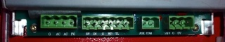
The laser-on and PWM signals from the power supply are on a 6-pin green connector (P2). Originally there is only a two-pin connector on the laser-ON. You need to make two new cables with JST connectors to connect the laser ON and PWM signals.
Note - The PWM signal needs to be connected to the "Exhaust Enable" output at this moment, due to SW issues. You may also leave it unconnected if you only want to use manual power adjustment.
| Pin | Signal | Function | Connect to |
|---|---|---|---|
| P2.1 | 5V | +5V from power supply | J37.1 (Exhaust enable C). Remove original Blue wire and connect it to J37.2 (Exhaust enable E). The blue wire supplies 5V to the potentiometer. |
| P2.2 | IN | Laser power setpoint (0..5V) | Red wire (leave connected) |
| P2.3 | G | GND | J39.4 Laser-on E and leave black wire (laser test) and yellow loop connected |
| P2.4 | WP | Laser supply enable | Leave yellow loop to GND connected |
| P2.5 | L | Laser ON input | J39.3 Laser-On C, leave black wire (laser test) connected |
| P2.6 | N.C. | N.C. |
Updated by Anonymous over 13 years ago · 4 revisions