Forums » Discussion and support »
 Getting started with LOAS REV3 + "HPC2" PowerSupply
Added by jamesc almost 13 years ago
Hi All,
This some notes for those with a HPC with the Green Connectors powersupply
http://wiki.laoslaser.org/index.php/Installation_HPC2
And the REV3 PCB
http://wiki.laoslaser.org/index.php/Mainboard_Rev3
I did it the hard way, mostly because I blew up the Polu drivers and installed the wrong firmware. Had I not made those mistakes the whole thing probably can be done in 15 minutes once you have soldered your board.
1. Solder the Board
Follow the wiki for this one.
http://wiki.laoslaser.org/index.php/Mainboard_Rev3
TIP: Actually you dont need all the parts.. Refer to this image
http://wiki.laoslaser.org/index.php/File:Mainboard_v0.3.jpg
TIP: Make double sure the servos are connected the correct way. With Polus the POT will be to the outside. With Stepstick the POT will be to the inside.
TIP: The JRT sockets all face-outwards, ie the side with the cuts/holes is on the outside of the board
TIP: Solder up all 3 microstep solder pads on the underside. Refer to the wiki page
2. Solder the I2C LCD Board
You should also solder the I2C board and make up a I2C cable.
http://wiki.laoslaser.org/index.php/I2cPanel
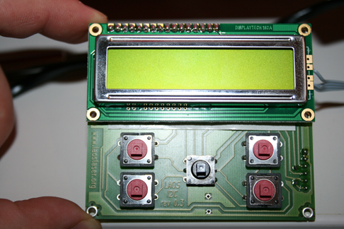
TIP: Make sure the buttons are on the top
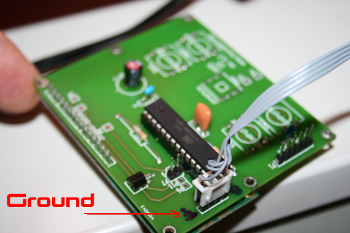
TIP: Make sure you get the polarity right when creating the cable. The GND on the I2C board is on the top side, ie closest to the upper edge.
3. Cables
The wiki page is really scary, but actually its super simple. IF you are not going to use the PWM feature then you only need to do 1 thing
TIP: For the cable with only 2 wires - green & yellow. Move the green wire from pin2, to pin4. This is the same as for the other power supply.
- Connect the flat cable into the flat cable connector making sure the metal contacts are both on the same side. This does both the X stepper motor and connects the sensors for the home position.
- Connect the Y Stepper motor cable into the connector next to the Y stepper motor driver.
- Connect the power supply cable
4. Test1
- Leave off the laser on/off cable ( the last one with only 2 wires green/yellow) disconnected for safety
- Attach the mBed using USB cable. You should have access to a hard drive where you can copy the test program
- Copy the test program(attached) onto the mBed hard disk
- Create a terminal session and attach to the mBed virtual serial port on mbed port, 115200, 8, N, 1 - I used windows hyperterminal
- Power on the HPC with the key
- Press reset on the mBed and you should see serial communication of the test program.
TIP: when you first power on you should hear a bit of a thump as the stepper motors activate
Press 'i' to make sure the i2c display panel is ok
Press 's' to make sure the SD card test is working. This is important one to pass.
Press 'x' and hold the key down, the steppers should start moving the X direction - very slowly.
Repeat for 'y' and X,Y to change the direction.
The settings of the POT are quite important. I have both Polu and stepstick drivers. The polus seem to do a better job. If the Stepsticks have too high a gain the stepper motors seem to jump around and get quite hot. I used a small screw driver to turn the pot while the power was on to sort of listen for the quiet spot where the drivers seemed to operate best. In any case I settled on the polus as they seemed to be working better and at lower temperature.
5. Test2
Turn power OFF
Remove the two stepper motor drivers
Turn power ON again
manually move the laser head to the top right hand corner.
You should see the blue leds activate as you hit the home position micro switches
6. READY to go.
Turn power OFF
replace the stepper motor drivers - DOUBLE CHECK THEY ARE IN THE CORRECT ORIENTATION.
Copy the Run program ( Attached) onto the mBed disk drive
Copy the config file (Attached) onto the mBed disk drive
Connect a Ethernet Cable to the Board
TIP: Configuring Ethernet
- This is the most user dependent part. I have a broadband router which my PC and my LOAS board both connect to. The broadband router then is the DHCP server so when the config file has DHCP 1 option the router will allocate an IP address dynamically. Normally this will always be the same IP address. In my case its 192.168.2.101 for the mBed/LOAS. This means when I ping from my PC I can ping the 192.168.2.101 address and receive a response. The LOAS/mBed service is on port 69 so the way to access the service for me is to use 192.168.2.101:69
Hold reset down on the mBED
Turn power ON
Release reset
TIP: The board will start powering up and if you have your communication cable attached and your communications terminal active you will start to see the output of the startup. First it tries to get the IP address it will use. This can be seen in the I2C display but if you dont have one you will need to have the communications terminal running to see the IP address you can use to access it.
7. HOME!
If all is well the IP address will be reported and the Laser will start heading to the HOME position.
8. Testing the Laser
Now you should connect up everything else if you havent done so already. The exhaust fan, the air supply, the water pump. You shuold make sure the water is flowing through the system before you try to activate the laser. Once thats all running you can do a first laser test.
With the power off
Using a the knob to move the base plate and use the focus square to align to the focus position - refer to the HPC booklet
Put a sheet of paper in
Close the cabinet
Turn on the power
Toggle the laser power on
Hold the right laser button down and quickly press and release the left side laser button
The analog needle should quickly move up and down
Toggle the laser power off
turn off the power
You should now have a small hole in your paper
9. Cutting a square
Attach the laser on/off cable previous left disconnected
Download the visicut software
Follow the instructions on this site to configure the LOAS machine - I used 192.168.2.101:69 but your IP address could change
Import the attached PCB.svg file to VisiCut
Power on the Laser Machine and when its ready
Press Execute
The I2C Display should show you received a job to print
Use the Joystick on the I2C display to select the job to print and push down the joystick to execute it
The laser should now operate and cut out the square!
Power down the laser
.. go have a beer!
Cheers,
James
| laos_iotest_board_LPC1768.bin (42.1 KB) laos_iotest_board_LPC1768.bin | Test Program | ||
| laoslaser_LPC1768.bin (111 KB) laoslaser_LPC1768.bin | Run Program | ||
| config.txt (3.23 KB) config.txt | Config File | ||
| PCB.SVG (861 Bytes) PCB.SVG | Square |
Replies (3)
RE: Getting started with LOAS REV3 + "HPC2" PowerSupply
-
Added by jamesc almost 13 years ago
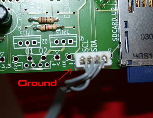
Some extra pictures of the I2C Display - I couldnt find any for reference on the laos wiki
| DisplayFront.png (378 KB) DisplayFront.png | I2C display with buttons on top | ||
| DisplayBack.png (378 KB) DisplayBack.png | I2C back with ground location | ||
| DisplayConnector.png (359 KB) DisplayConnector.png | Ground location of I2C connector on rev3 board |
 RE: Getting started with LOAS REV3 + "HPC2" PowerSupply
-
Added by Anonymous almost 13 years ago
RE: Getting started with LOAS REV3 + "HPC2" PowerSupply
-
Added by Anonymous almost 13 years ago
Great - I've made a note to put this on the wiki one day, see issue #2
 RE: Getting started with LOAS REV3 + "HPC2" PowerSupply
-
Added by pieterb almost 13 years ago
RE: Getting started with LOAS REV3 + "HPC2" PowerSupply
-
Added by pieterb almost 13 years ago
Aaah i did the laser test (8) with the laos_iotest_board_LPC1768.bin and with the laser on/off cable attached, that may account for the strange behavior (it seems the iotest has the laser turned on by default, if thats is the case, it should be changed ;-).
Thanks for this step by step .