Assembling the LAOS electronics boards » History » Revision 3
« Previous |
Revision 3/14
(diff)
| Next »
jaap, 2012-08-15 11:23
- Table of contents
- Assembling the LAOS electronics boards
- Board version, layout and schematics
- Soldering the board
- Testing the board
- TestfirmwareNow you should be ready to load the TestFirmware
Assembling the LAOS electronics boards
Board version, layout and schematics

- Rev 0.1 has some very visible bugs. One of the is that the LED connectors have no pre-tinned pads on both sides of the board, but only on the top side. If you see that, you most definitly have Rev 1. See Mainboard_Rev1
- Rev 0.2 has a LaosLaser LOGO under the SD. Rev 0.1 does not, and Rev 0.3 also doesn't have it! See Mainboard_Rev2
- Rev 0.3 has no LOGO, but it says LAOS Board v0.3 just above the MBED.
The older boards have small bugs, but none of them is bad enough to replace your old board with a newer one. The bugs can be fixed with simple soldering solutions, making the boards just as good as Rev 0.3.
Before you start soldering:- read the LAOS_Mainboard_v03 page and make sure you have the parts you need
- download layout and schematics PDF's:
https://tuxic.nl/laos/hardware/pcb/laos-board-rev3/output/laos-board-rev3.pdf
https://tuxic.nl/laos/hardware/pcb/laos-board-rev3/production/PI_E453774.pdf
Soldering the board
SD card socket
Solder the SD card socket in place first, as it is the only SMD component and it's nice to have some space around it when soldering.
DIL Sockets
Place the two DIL sockets the opto-couplers (OPTO-IN, OPTO-OUT) and the one for the CANBUS chip (optional) and solder them in place, keeping the dent on the same side as indicated on the board.
MBED footprint
Solder two rows of pin receptacles in place for the MBED. The outer rows are optional (debugging or expansion only).
Pololu only
If you want to use Pololu stepper drivers or the compatible [http://reprap.org/wiki/StepStick StepStick] drivers:
Solder in the two rows of pin header sockets for each Pololu.- J8: Z-Axis
- J17: Y-Axis
- J23: X-Axis
- J32: Extra (Extruder, Rotation) Axis (probably you can skip this one for a laser)
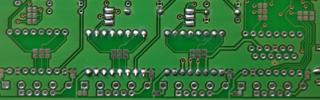
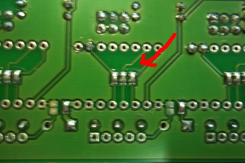
On the back side of the board, there are 3 x 2 solder pads next to the Pololu headers. With these solder pads you can enable microstepping on the Pololu's. If you connect all of them, you get the maximum number of microsteps. '''Note:''' do not connect the solder pads '''inside''' the Pololu footprint. These should be connected only if you are using externals stepper drivers instead of Pololu's.
Non-Pololu only
If you're not using Pololu-compatible stepper drivers on the mainboard but some other ''external'' stepper driver boards:- Connect the solder pads on the back of the board (under the Pololu footprint) two by two
- GND: this can be enabled on the outgoing connectors by filling the solder pad under the connector.
- Some voltage: you can use Vmot by filling the solder pad under the connector (the square pole is +). If you need 3V3 you can make a wire between the pololu pins (10) and (14). If you need 5V, you can make a wire from a 5V net to pololu pin (14).
If you need all five pins, the standard Phoenix connectors will not fit, so you will have to get Phoenix mini or other connectors (e.54mm pitch).
Resistors
Find the resistors and put them in the print.| Value | Count | Resistor numbers |
|---|---|---|
| 100 Ohm | 1 | R34 |
| 120 Ohm | 1 | R1 |
| 330 Ohm | 4 | R28, R29, R31, R32 |
| 1K | 15 | R2, R3, R6, R11, R12, R14, R15, R17, R22, R23, R24, R26, R27, R30, R33 |
| 2K2 | 2 | R7, R8 |
| 10K | 11 | R4, R5, R9, R10, R13, R16, R18, R19, R20, R21, R25 |
Bear in mind that R8 (which sits underneath R7 may have a trace crossing it so it may appear like R6), make sure that this is not the case, the real R6 is part of the R4, R9 and R6 row).
You can solder in all resistors, or omit the ones you don't need. We advise to leave out resistor R10 and R12 for now, because these can do BAD THINGS (tm) to your MBED if you choose the wrong value. Their correct values are handled in a later chapter.
Resistor list
| Number | Value (Ohm) | Function | Common | Optional |
|---|---|---|---|---|
| R1 | 120 | Can Bus | Only needed for Can Bus | |
| R2 | 1K | Magjack LED | X | Only needed for Magjack with LEDs |
| R3 | 1K | Magjack LED | Can be omitted, also when Magjack has LEDs! | |
| R4 | 10K | Enable LED | X | If you do not want LEDs on your board, this resistor is not needed |
| R5 | 10K | VMOT LED | X | If you do not want LEDs on your board, this resistor is not needed |
| R6 | 1K | Z Axis Pololu Microstepping Pull-UP | Only for machines with Z-Axis and Pololu | |
| R7 | 2K2 | I2C | X | Only for machines with I2C display |
| R8 | 2K2 | I2C | X | Only for machines with I2C display |
| R9 | 10K | Z Axis Pololu Microstepping Pull-Down | Only for machines with Z-Axis and Pololu | |
| R10 | J14 AIN Pull-UP | Only needed if J14 is used | ||
| R11 | 1K | Y Axis Pololu Microstepping Pull-UP | X | Only needed on machines with Pololu |
| R12 | J14 AIN Pull-Down | Only needed if J14 is used | ||
| R13 | 10K | Y Axis Pololu Microstepping Pull-Down | Only needed on machines with Pololu that do not do full microstepping | |
| R14 | 1K | X Axis Pololu Microstepping Pull-UP | X | Only needed on machines with Pololu |
| R15 | 1K | J27 Analog output signal | Only if J27 is used | |
| R16 | 10K | X Axis Pololu Microstepping Pull-Down | Only needed on machines with Pololu that do not do full microstepping | |
| R17 | 1K | J27 Analog output signal | Only if J27 is used | |
| R18 | 10K | YHOME Pull-UP | X | |
| R19 | 10K | XHOME Pull-UP | X | |
| R20 | 1K | E Axis Pololu Microstepping Pull-UP | Only for machines with E-Axis and Pololu | |
| R21 | 10K | ZMIN Pull-UP | Only for machines with Z-Axis | |
| R22 | 10K | ZMAX Pull-UP | Only for machines with Z-Axis | |
| R23 | 1K | ZMAX OPTO | Only for machines with Z-Axis | |
| R24 | 1K | ZMIN OPTO | Only for machines with Z-Axis | |
| R25 | 10K | E Axis Pololu Microstepping Pull-Down | ||
| R26 | 1K | XHOME OPTO | X | |
| R27 | 1K | YHOME OPTO | X | |
| R28 | 330 | Exhaust OPTO | X | All machines, because exhaust out is used for PWM right now! |
| R29 | 330 | Laser Enable OPTO | X | Not in use, but advise to solder it in anyway! |
| R30 | 1K | 5V Power LED | X | If you do not want LEDs on your board, this resistor is not needed |
| R31 | 330 | Laser PWM OPTO | X | |
| R32 | 330 | Laser ON OPTO | X | |
| R33 | 1K | AIN voltage divider | Only if AIN is in use | |
| R34 | 100 | AOUT current limit | Only if AOUT is in use |
Capacitors
Place the capacitors:
| Number | Value | Function | Comment |
|---|---|---|---|
| C1 | 100 nF | Magjack noise filter | |
| C3 | 100 nF | VMOT noise filter | |
| C4 | 1000 uF Elco | VMOT buffer | make sure the + goes through the square hole. |
| C5 | 100 nF | AIN noise filter | Can be omitted if AIN is not used |
| C6 | 100 uF Elco | VCPU Buffer | make sure the + goes through the square hole. |
| C7 | 22 nF | VCPU noise filter | Can be omitted if no voltage regulator (7805) is used |
| C8 | 100 nF | +5V noise filter |
LEDS
Place the 3 leds, matching the flat side of the LED with the flat side of the led-drawing on the pcb. It's hard to see, but there is a flat side on the circles!
USB connector and network connector
Place the USB and network connector. The USB is currently not used, so it's optional.
Connectors
Choose connectors that fit your laser best. Examples:
Default configuration
- 7 4-pin phoenix connectors:
- X, Y, Z connectors (J24, J18, J9)
- XY endswitch, Z-/Z+ endswitch (J34, J29)
- Laser P1,P2 (J37)
- PWM out (J27)
- 3 2-pin phoenix connectors
- Laser P4 (J39)
- Power supply (J38)
- Cover lid switch (J14)
- 1 5-pin phoenix connector (which is actually not in use at all!)
- J33
- 1 4-pin header
- I2C (J10)
HPC LS-3020
- 4-pin JST connector on Y-axis (J18)
- 4-pin JST connector on J38 (laser ON/PWM)
- flatcable connector on P1 (X-axis, X+Y endstops)
- 3-pin Phoenix/Wuerth connector on J5 (Power)
- 4-pin JST connector on J10 (I2C)
HPC LS-3020 Pro
- 4-pin JST connector on Y-axis and X-axis (J18, J24)
- 4-pin JST connector on J38 (laser ON/PWM)
- 4-pin JST connector on J34 (X+Y endstops)
- 3-pin Phoenix/Wuerth connector on J5 (Power)
- 4-pin JST connector on J10 (I2C)
Transistors
- Solder in the two Darlington PNP Transistors (optional)
Powering the board
The board offers several options for getting power:
variable options
- J38 can be used to connect power for the board. The input power should be between 5 and 12 volts. If the power level is exactly 5V, the 7805 can be omitted and should be short-circuited with a wire between pole 1 and 3. If the power is higher then 5V or coming from a cheap adapter, using the 7805 is recommended.
- J5 can be used as a two-pole connector for VMOT (motor power for Pololu steppers). It can also contain the board input power on the 3rd pole, but then J38 should be omitted.
- Finally, J5 can be used to supply the same power level as input to the board AND to as motor power to the steppers by making a jumper wire on the connector just above J5 (next to the sign "exhaust enable").
HPC 3020 laser
The HPC laser comes with a plug with 5V and 24V combined. This can be connected to J5. The 7805 should be omitted and replaced by a jumper wire between pole 1 and 3.
R10 and R12 resistors
Depending on the use of J14 and the power on VMOT, determine the correct values for R10 and R12.
Power Jumpers
The board contains 2 extra power jumpers to select power on inputs
VEndstops Voltage selection
Place pin header on J43 for voltage selection on the sensors. This is the four-pin T-footprint near the endstop terminals.
For HPC LS3020, connecting the middle pin with +5V with a wire will do.
VSensor (J27) Voltage selection
The second power jumper is a 3-pin jumper labelled VCPU/VSENSOR/5V. It is located between the MBED and the 100 uF capacitor. This can be connected in two ways:- VCPU -> VSENSOR: use VCPU as the power level for the sensors.
- 5V -> VSENSOR: use +5V as the power level for the sensors.
Connect only one of the outer pins with the middle pin at the same time!
PWM Output select jumpers
01SRC/02SRC: select which pwm value is send to the transistors.
Testing the board
Visual double check
Check your board without power, to see if everything is al right- visually check all solder joints
- check all soldered wire-bridges and jumper settings
Power check
First remove the MBED, SDCARD, POLOLUs, OPTO-COUPLERS
Power check 1
- apply power (CPU and motor).
- Now check the voltages on the pins of the MBED (5V on pin 2, no voltages on other pins)
- Check 24V (or other Vmotor) on the pololus
- check ground connections on POLOLUs (by measuring between 5V and those pins)
Power check 2
- disconnect power
- place the MBED (with usb connector on top = side of network connector)
- connect the MBED to your PC or USB hub with the USB cable
- Check all 3V3 voltages
- Pololus
- Opto-couplers
- SD-card
If you are absolutely sure all power connections are OK, install the other components and proceed with the functional tests.
WRONG JUMPER CONNECTIONS OR BAD SOLDERING CAN CAUSE YOUR COMPONENTS (OR EVEN YOUR COMPUTER) TO START SMOKING AND CAUSE A LOT OF DAMAGE, MAKE SURE YOU CHECK AND DOUBLE-CHECK EVERYTHING BEFORE CONNECTING THINGS
Placing OPTO-Couplers
The KB847 chips have a tiny line on one side. With the notch on the top, this is the left side of the chip. So on OPTO-IN, the line should be on the side of the SD card. On OPTO-OUT the line should be on de side of the MBED.
Put the Opto-coupler IC's in place, and the CAN chip and test again. Place a (max 2GB) SD card.
Testfirmware
Now you should be ready to load the TestFirmware
Updated by jaap over 13 years ago · 3 revisions