Bug #50
closed
Change CAN bus connector to RJ11/RJ12
100%
Description
The Tosca project has selected RJ11 as CAN bus connector. It might be an idea to adopt it here as well. That's a 6-pin jack with the centre 4 wires as follows:
- +5V
- CAN-H
- CAN-L
- GND
From what I can tell, pinout is the same as now - could also be added extra (same space), so that 4-pin 0.1" header can still be used instead.
Files
| rj12-detail.png (36.4 KB) rj12-detail.png | |||
| board.png (29.5 KB) board.png | |||
| canrj10.jpg (7.8 KB) canrj10.jpg | |||
| chip.png (12.9 KB) chip.png |
 Updated by jaap over 13 years ago
- Category set to Mainboard
- Status changed from New to Resolved
- Assignee set to jaap
- Target version set to Laos Mainboard Rev4
- % Done changed from 0 to 100
Replaced connector with RJ12
Updated by Anonymous over 13 years ago
- File rj12-detail.png rj12-detail.png added
Consider bringing out pins 1 and 6 to some pads. They will optionally have 12..24V power (for smaller setups, limited current capability), so hooking them up may come in handy.
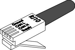
I don't have engineering drawings, but I've used these jacks (have hundreds of 'em here if you needs some...) on a JeeLabs design, see this page.
Looking at the Tosca image (source), the plug, and the LaOS rev4 board, I don't think this pinout is correct, though. On the plug I have here, the middle 4 contacts are also the middle 4 pins. On the rev4 board, I see this:
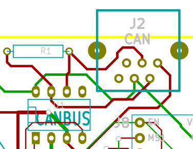
Update -fixed on 2012-10-01: proper link to RJ11 for CAN, as defined in CANopen.
Updated by jaap over 13 years ago
Ok, so this might be it. But is + on the right side?
Updated by Anonymous over 13 years ago
Sorry to bother you with this, but could you update the two SVG's as well?
Updated by jaap over 13 years ago
I see that this pinout here: http://jeelabs.net/projects/hardware/wiki/Utility_Plug has +3V and GND in the middle, whereas I put GND and +5V on pin 2 and 5. Which one should it be?
BTW:svg's have been updated on github now...
Updated by Anonymous over 13 years ago
Ignore the Utility Plug pin assignment please, it's not related to Tosca or CAN. Just wanted to point to an example of use. I've included an example of that board in the package going out to you today.
Updated by Anonymous over 13 years ago
- File board.png board.png added
- File canrj10.jpg canrj10.jpg added
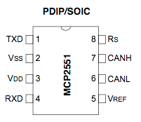
- File chip.png chip.png added
Some more background - the outer two pins are not used for CAN, but will be optionally connected in Tosca. Here's the pinout I'd propose for the 6-pin header you attached:
(OPT24V+) +5V CAN_H CAN_L GND (OPT24V-)Here are all the images again, for reference:
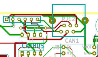
Looking at the RJ12 jack from the board top as oriented above, supply/power should be on the righthand side.
My guess would be:
     GND     CAN_H   (24V+)
(24V-)   CAN_L    +5V
The two 24V lines should not be attached other than to the 6-pin 0.1" header, but I'd use thick traces if possible, so that it might support bus-powered use of LaOS one day.
Updated by Anonymous over 13 years ago
Sorry for the confusion - RJ12 pin names should match up now.