HPC LS3020 connections - July 2012 » History » Revision 13
« Previous |
Revision 13/16
(diff)
| Next »
jaap, 2012-08-14 16:40
HPC LS3020 connections - July 2012
- Table of contents
- HPC LS3020 connections - July 2012
Wiring diagram
Here is a schematic diagram of how everything should be wired up (see ):

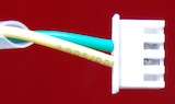
Laser ON cable
The laser-on cable, as it comes shipped with the laser cutter needs to have one wire switched over, from this:
 ... to this:
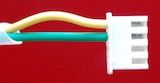
It then plugs into the mainboard like this: 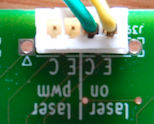
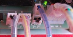
Disabled laser PWM
To get started fast, just run the laser without PWM support - you can accomplish the same by manually turning the front-panel potmeter back to reduce the power.
With the July 12 power supply, you're done. To disable PWM on the older power supply, make sure the D+ and D- pins are jumpered on the power supply:
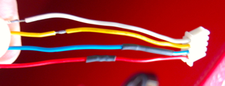
Y stepper cable
The Y stepper cable (with a 4-pin JST connector on the end) may be too short to reach the proper socket on the LAOS mainboard v0.3 - this can be solved by manually splicing some extra wires, to extend it by about 15 cm:
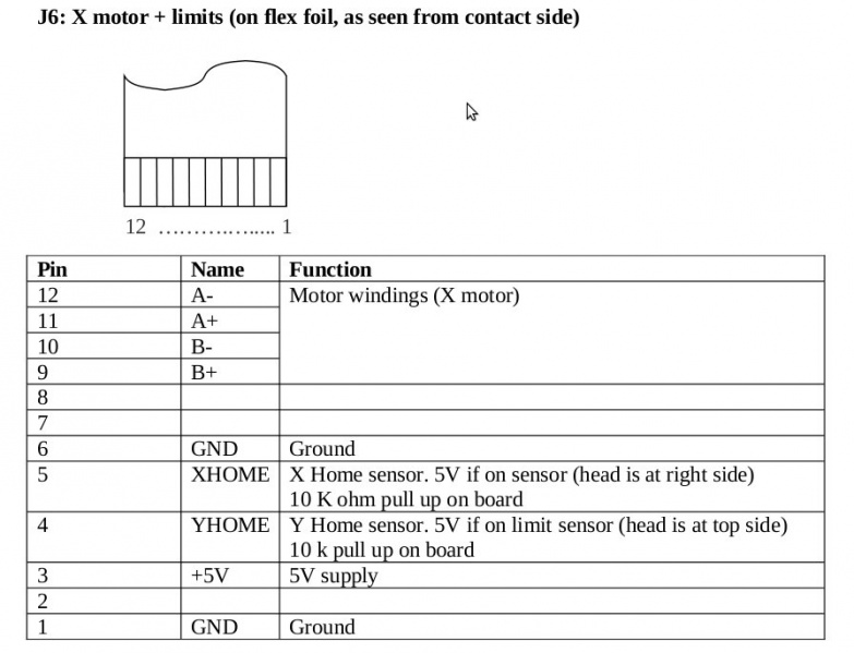
Flatcable for X stepper and endstops
| Pin | Signal | Connect to |
|---|---|---|
| PIN12 | XA- | J24.1 A |
| PIN11 | XA+ | J24.2 A |
| PIN10 | XB- | J34.3 B |
| PIN9 | XB+ | J34.4 B |
| PIN6 | COMMON | J34.4 GND |
| PIN5 | XHOME | J34.2 XHOME |
| PIN4 | YHOME | J34.3 YHOME |
| PIN3 | +5V | J34.1 Vsensor |
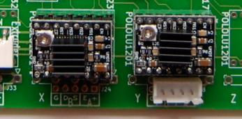
Stepper driver orientation
Be very careful how you place the stepper drivers on the mainboard. Mistakes can blow up both the stepper driver and the mbed controller!
Here is the proper orientation for the purple "StepStick" drivers, with heatsinks mounted on top of the A3984 driver IC's:
Updated by jaap over 13 years ago · 13 revisions