Pwm » History » Revision 13
« Previous |
Revision 13/19
(diff)
| Next »
peteruithoven, 2013-03-06 01:47
PWM
PWM stands for Pulse Width Modulation and is used to control the power of the laser. On the HPC3020 you will see a mA meter and a turn knob that will allow you to control the power of the laser by hand. With PWM the Laos board can take over this function, which allows for e.g. engraving of pictures or controlling the right power settings for certain materials.
Based on the laser power supply, there are different connections required.
In general we can identify 3 cases:- Only "Laser ON" signal connected to the power supply
- Seperate "Laser ON" signal AND "Analog power" (PWM) input used on the laser power supply
- "Laser ON" and "PWM" signal combined (not covered in this description)
The outputs of the Laos board have opto-couplers that need to be connected to the right pins of the power supply. Usually a pull-up resistor is required between the collector of the opto-coupler and 5VDC. The emitter of the opto-coupler is connected to ground. In some power supplies the pull-up resistor is already present, on some inputs an additional resistor is required.
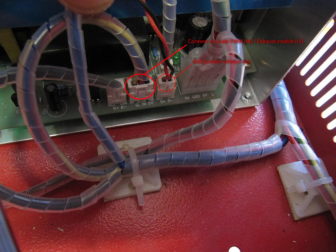
Example of enabled laser PWM
To use the power control from the LAOS board, you need to connect the laser PWM output to the ANALOG input of your power supply.
Note: There is a difference between the PWM connections of boards with revision<3 and board revision >= 4!
Revision 3 boards: "Laser PWM" output is actually on the "Exhaust enable" connector (J37 PIN 1 and 2)
Revision 4 boards: "Laser PWM" output is correctly on the "Laser PWM" connector (J39 PIN 3 and 4)
Connection of the PWM signal together with the analog potentiometer
Some people have connected both the original potentiometer and the PWM output. While this does work, the linearity of the power setting is very bad. It is not advised to have both connections at the same time. Replace the potentiometer with the PWM output.
Connection of the PWM to the analog input of the power supply (GND/IN/5V)
Use a 470 ohm (0.25W or more) pull-up resistor between +5V and analog in at the laser power supply side.- "C" connects to the analog IN pin (and 1 side of the resistor, the other side connects to 5V on the power supply)
- "E" connects to GND
The laser side of the connection can be on a 3 pin JST connector or the large GREEN connectors, depending of the power supply type.
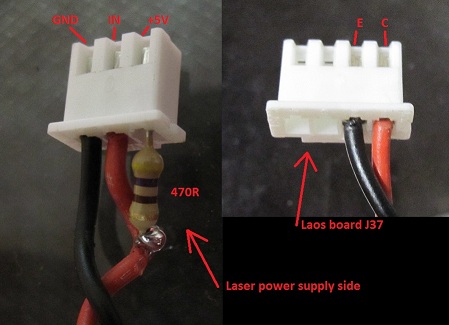
This image is slightly confusing because the 4 pin JST is also connected using 2 cables to the laser on connection (but not rev 3).
HPC3020 laser
hpc side, very much a poc (a what?) (How do I recognize the analog input? The image doesn't really help)
laos side
KIII laser
?
Updated by peteruithoven almost 13 years ago · 13 revisions