Forums » Discussion and support »
 Setting up LS3020 & homing issues
Added by jimjiminyjimjim almost 12 years ago
I've just connected my LAOS board to my HPC LS3020. I haven't connected the laser power lead yet but have already encountered a few issues that don't seem quite right...
- On the test setup .bin, I get all the correct serial messaging through to my monitor app - but when I press and hold the X or Y key I get no movement from the laser cutter. I tried the full version of the .bin and the laser cutting head moves absolutely fine in both directions - so wasn’t sure if it was a symptom of something. When I use the I2C panel to move in X or Y it moves with a 3 speed increment with every touch of the joystick i.e it starts moving slowly, then a little faster, then faster still and then stops. Is this normal? Or is this a pololu trim issue maybe?
- The main issue is that it only homes in the X direction. It never tries to home in the Y direction. I changed the config.txt file to change the polarity of the Y homing - it did try to home Y in the right direction but continued to far and crashed into the side of the machine and kept going, as if it never activated. I thought maybe it was a fault with connections - but I’ve swapped in the original HPC board and it still homes just fine. After reconnecting the LAOS - the same problem exists. The only other thing I can see related to this is that in the read out of the test .bin file - I get Xhome 0 and Yhome 1- Does this mean that it thinks its already at the home position?
Thanks for your help.
Replies (23)
 RE: Setting up LS3020 & homing issues
-
Added by jaap almost 12 years ago
RE: Setting up LS3020 & homing issues
-
Added by jaap almost 12 years ago
The X/Y motion with the test Firmware is so little that it doesn't really show. There is feature to send a number of pulses at once, just enough for some small motion. This feature is not documented on the wiki but it does show in the option list you get on your serial connection.
With the normal firmware, jogging with the joystick doesn't really work properly at the moment. You can move the head, but it's not very fluent.
If homing in the Y-direction doesn't work, it might be that your endstop isn't working properly. You can test this by loading the Test Firmware. If you push the Y endstop by hand,
you should see LED2 of the Mbed go on/off. [[http://redmine.laoslaser.org/projects/laos/wiki/TestFirmware]]
- if homing happens in the right direction. There is only one endstop, so it should go there and not to the other side.
- if the polarity of the endstop is configured right. It might be you need to change that in config.txt
Values to play with:
y.pol     0/1  Polarity of the home/limit sensor
y.homedir 0/1  Home direction
y.scale        Use positive or negative value to change direction of Y-axis
y.invert       Change polarity of the pulse signal for this axis
[[http://redmine.laoslaser.org/projects/laos/wiki/LAOS_configuration_file]]
RE: Setting up LS3020 & homing issues
-
Added by jimjiminyjimjim almost 12 years ago
Thanks Jaap.
I took a quick look around - can you tell me where you find the Y endstop on a 3020?
RE: Setting up LS3020 & homing issues
-
Added by jaap almost 12 years ago
There are a few small differences in the machines. On my HPC-3020, it's on the right side of the frame, under the X-portal. Follow the flatcable, then you should find it!
RE: Setting up LS3020 & homing issues
-
Added by jimjiminyjimjim almost 12 years ago
I've had a good look around and really can't see any endstops?!
What am I looking for? I've got a 3d printer that has switches - is it similar?
Also whats the X-portal?
 RE: Setting up LS3020 & homing issues
-
Added by peteruithoven almost 12 years ago
RE: Setting up LS3020 & homing issues
-
Added by peteruithoven almost 12 years ago
Hi Jim?,
Yeah, it's the same kind of switches, it's all quite similar. Usually 3D printers have endstops on both sides of axis and lasercutters and cnc mills only on one side. 3D printer switches are a bit smaller.
You can hear a clicking sound when a endswitch is pressed, so you could locate them by sound.
The X-portal is the bar that moves in the vertical direction and on which the head moves in the horizontal direction.
RE: Setting up LS3020 & homing issues
-
Added by jimjiminyjimjim almost 12 years ago
Hi Peter,
I've attached two images of what seems to be my endstops. These don't look like microswitches - are they magnetic? There seems to be a small metal 'prong' on one side and then a green piece of plastic that the ribbon cable goes into. For both X & Y.
I've uploaded the test file. And 3 lights out of 4 are lit on the board. If I move the X axis to home, then I get all four lights lit. Nothing happens when I push the laser to the Y axis home position. Not sure how to activate them other than moving that axis about. It is As the plotter homes fine with the original board - it would suggest that the Y homing does work mechanically?
This is the output from the test file -
.......
LaOS Test program
++++++++++++++++
Use these keys to test functionality
xX: X Step/Dir.yY: Y Step/Dir.zZ: Z Step/Dir.tT: Ext Step/Dir
e: Toggle Stepper enable
s: SD-Card
i: I2C
1/2/3/4: Outputs
Test e: enable is now ON
xhome=0, yhome=1, zmin=1, zmax=1
.... as you can see Yhome is always 1. I've tried switching each of these values but it doesn't seem to have an effect:
y.pol 1 ; home/limit sensor polarity [1/0]
y.invert 0 ; Invert signal polarity for step signal [1/0]
RE: Setting up LS3020 & homing issues
-
Added by jaap almost 12 years ago
Hi Jim,
At least it is clear something is wrong with the endstops, they should give the same value in the test program.
If you move the axis by hand, you should see the value change from 0 to 1 or 1 to 0 when touching the endstop.
If the endstops work when you use the original board, I can think of two possible problems:- there is something wrong with the wiring of the Y-endstop. You can swap the optical IC's (OPTO1 / OPTO2) to see if one of them is broken. And follow the wiring, maybe there is a resistor that is not connected well, or a missing resistor.
- the power is too low. Your endstop might need 12v instead of 5V. You could measure the voltage that goes to the endstops on the original board to make sure.
RE: Setting up LS3020 & homing issues
-
Added by jimjiminyjimjim over 11 years ago
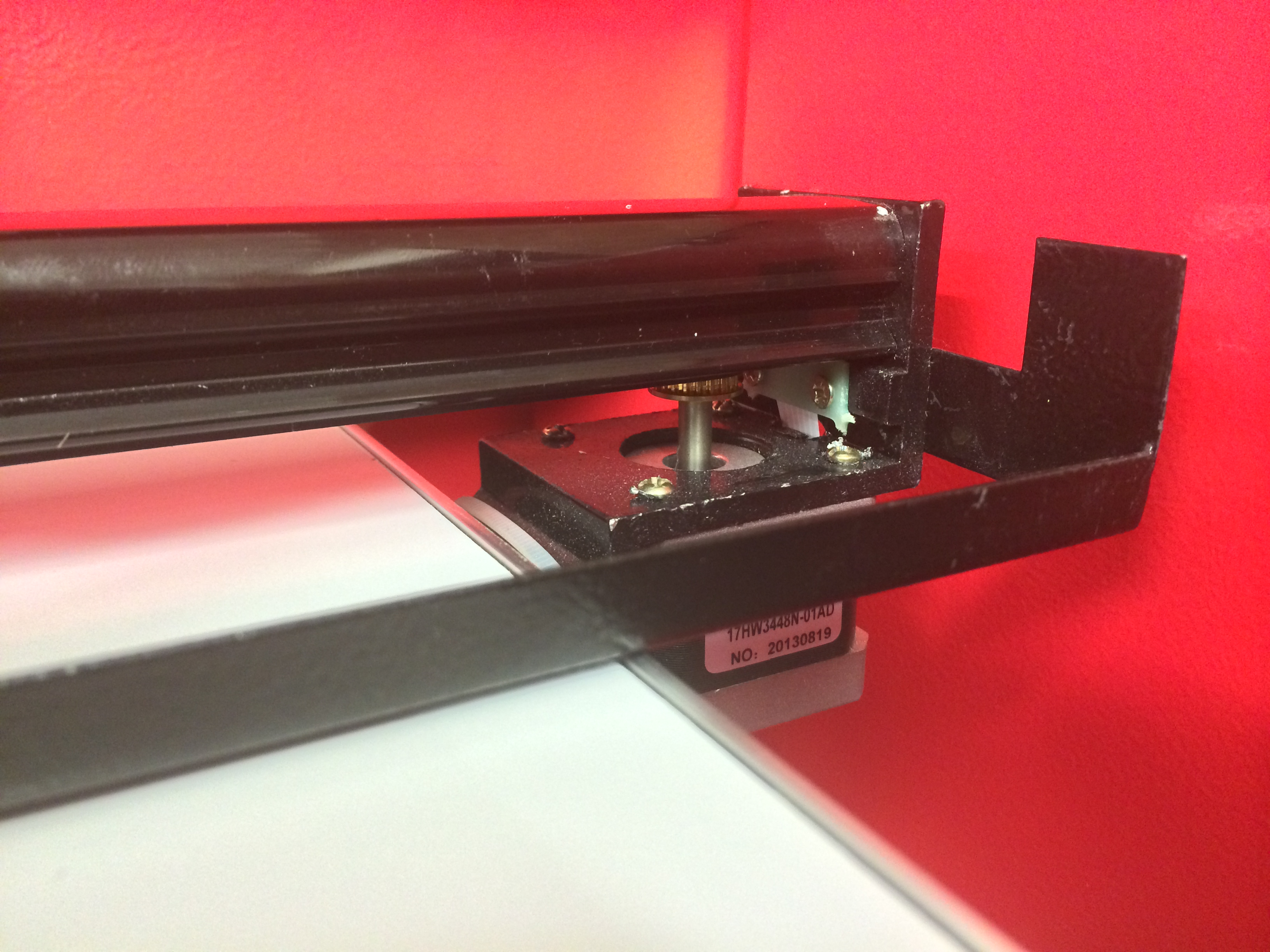
So I've finally removed the laser frame form the casing -
I measured the voltage on the old board when the endstop should be homed. This came out at 4.4V. When it wasn't homed it was 0V.
I measured the voltage on the LOAS board when the endstop should be homed. This came out at 0.4V. When it wasn't homed it was 0.3 / 0.4V.
I've attached an image to show which pins I was measuring.
Any ideas?
I can't easily get to the correctly functioning endstop to measure?
Are there any other settings of jumpers that could be effecting this?
Thanks.
RE: Setting up LS3020 & homing issues
-
Added by jaap over 11 years ago
Hi Jim,
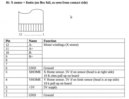
Near the JST connector for endstops (4-pin connector) on the board, there is a 3-way solder point for the endstop voltage. It's 4 holes and you should have the middle one connected to +5V.
On your LaOS board, you should measure 5V between the GND and VEndStops on connector J34. You can also measure the return voltage from the endstops on the two middle pins of J34. What do you measure there, for X and Y?
RE: Setting up LS3020 & homing issues
-
Added by jimjiminyjimjim over 11 years ago
Hi
So I've checked these readings...
- GND and VEndStops is about 4.7- 5 volts
- GND and XHome - is 0.3 unless homed at which point it increases to around 4.5-5
- GND and YHome - continuously on 4.2- 4.5Volts
Which makes sense as to why it thinks it homed.
I switched over the OPTO ics on the LOAS board but made no difference.
RE: Setting up LS3020 & homing issues
-
Added by jaap over 11 years ago
There is a note here, about GND issues on some lasers: http://redmine.laoslaser.org/boards/2/topics/545?r=575#message-575
If this is the same with your machine, you might need to make a wire from pin 1 to pin 6 on the flatcable.
If that's not the case, I think it must be that one of the wires to YHome is on a different pin with your machine. To find out which one, check which pins are "unused" on the flatcable: http://redmine.laoslaser.org/attachments/download/89/HPC-flat-cable-pinning.jpg For all of these pins, check with a multimeter if one of them has a connection to a pin on the Y Endstop. If so, then most likely this pin replaces one of the 3 connections to the endstop in your case, and you should be able to find out if this is +5V, YHOME or GND (most likely it's YHOME).
Be carefull when making shortcuts between pins, because the motor winding pins can have 24V! Also making a shortcut between +5V and GND is not nice.
RE: Setting up LS3020 & homing issues
-
Added by jimjiminyjimjim over 11 years ago
So I checked the continuity on the flat cable connections and it looks like its using Pin 2 instead of Pin 4 for Yhome - so it seems that is probably the reason.
How do I check that Pin 4 isn't being used for something else if I'm going to short? Some of the ends of the cable are next to impossible to get to without dismantling everything.
Is is possible to change the pin config in the firmware rather than hacking the electronics?
RE: Setting up LS3020 & homing issues
-
Added by jaap over 11 years ago
The pin-out of the flatcable (as we use it) is here: http://redmine.laoslaser.org/projects/laos/wiki/HPC_LS3020_connections_-_July_2012#Flatcable-for-X-stepper-and-endstops
Pin 2 is not in use, so it's not connected to anything on the LaOS board. You could just make a solder bridge between pin 2 and pin4 on the backside of the connector (on the board).
RE: Setting up LS3020 & homing issues
-
Added by jimjiminyjimjim over 11 years ago
Ok so after more investigation and double checking I'm not sure I do know whats going on.
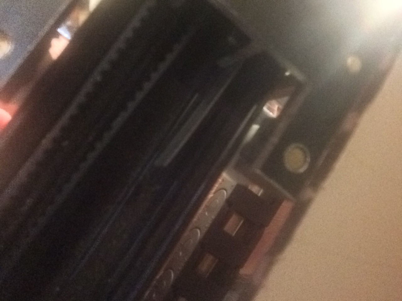
There are 4 pins on the back of my endstop. I've attached an image. 2 endstop pins go to the GND on pin 6 on the ribbon cable. 1 pin goes to pin 4 - which is expected? The fourth pin doesn't seem to be connected to anything on the ribbon cable pins?
So I was wrong about Pin2 instead of Pin4 - I was measuring the wrong thing.
I also could see the note about GND issues on this link... http://redmine.laoslaser.org/boards/2/topics/545?r=575#message-575
I'm not really sure what the issue is - but also I have a standard LS3020 - which everyone else seems to be using ok. Did they change the endstops on these at some point? What best for me to look at next?
RE: Setting up LS3020 & homing issues
-
Added by jimjiminyjimjim over 11 years ago
Is there anyone that can help me with this? I'd really like to get the board up and running - but I'm not really sure what I should be testing at this point?
Is the thinking with the ground issue that my PIN 6 needs to be connected to a different GND? What else can I test?
Any help would be much appreciated!
RE: Setting up LS3020 & homing issues
-
Added by jimjiminyjimjim almost 11 years ago
Ok - I'm determined to get my laser cutter up and running as is been sitting on the workbench in pieces.
Quick summary...
- X axis homing works absolutely fine
- Y axis doesn't seem to home
- Light continuously on suggesting it thinks it is homed. Checked the voltage and it doesn't seem to change from 4.5/5V when its in the home position.
- If I connect the old board back up everything works fine.
Have read about this GND issue..
http://redmine.laoslaser.org/boards/2/topics/545?r=575#message-575
but unsure if this applies to my laser cutter? Should I just try connecting pin1 & 6 together?
Other people seem to have HPC3020 up and running after me - so it would suggest that the LAOS is compatible with opto endstops. Could there be a problem with my board?
I'm fairly confident at debugging these things - but a step by step to help get to a diagnosis of a problem would really help.
Would it be possible for some help with this - otherwise my board its a pretty expensive coaster!!
 RE: Setting up LS3020 & homing issues
-
Added by Springuin almost 11 years ago
RE: Setting up LS3020 & homing issues
-
Added by Springuin almost 11 years ago
If one of the blue LED's on the mbed is still on, it is not homed yet. The normal procedure (in my machine) is that the machine switches on, two blue LED's turn on, the machine homes and as soon as it reaches the switches their respective LED turns off.
Checked the voltage and it doesn't seem to change from 4.5/5V when its in the home position.
That's wrong, the voltage on the home connection must change when you actuate the home switch otherwise it's not working. Check continuity between connections on the Laos board and the pins of the switch.
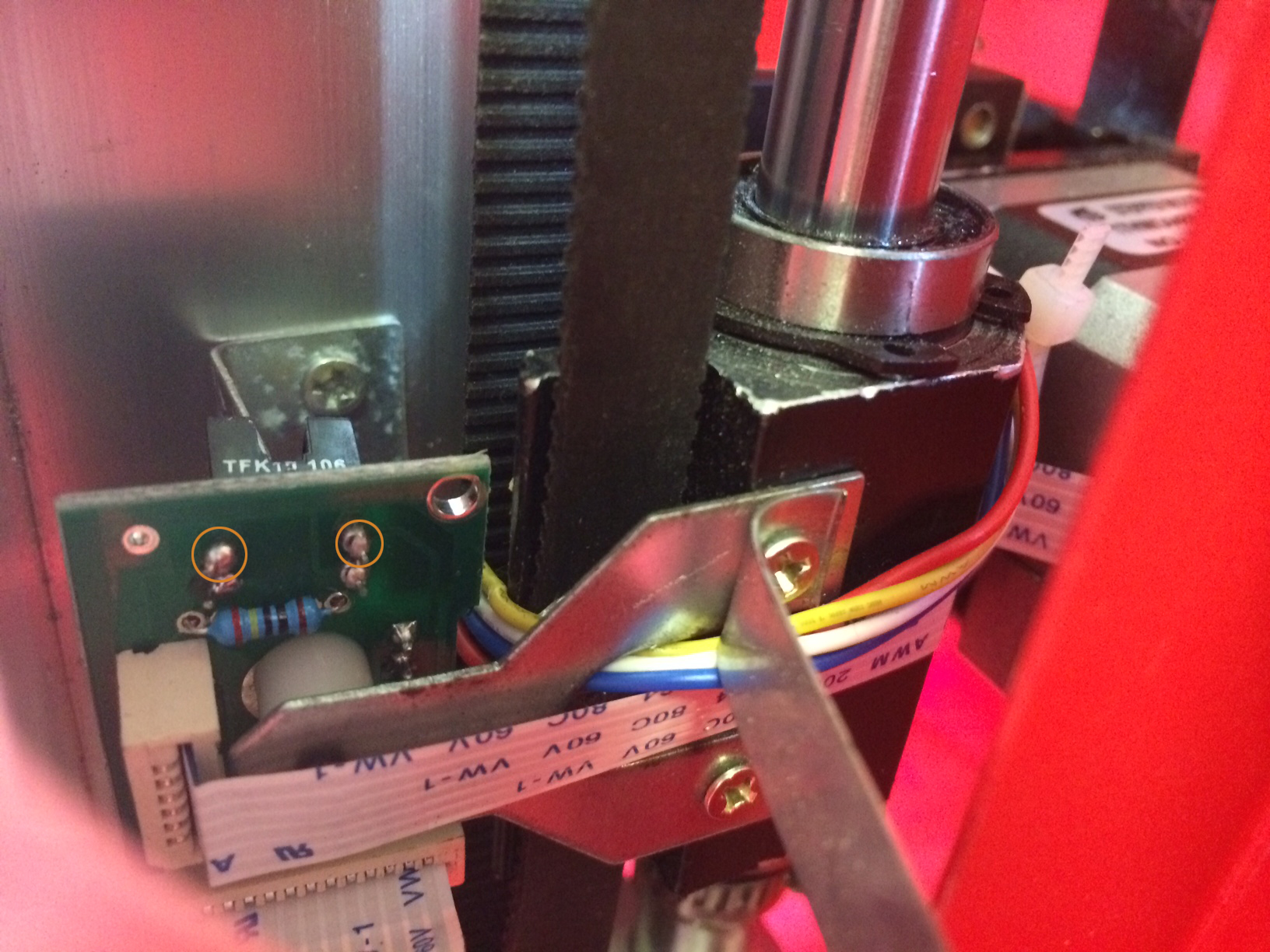
A few pointers:- I see you have an optical end-switch instead of the more common microswitches. If you can remove that endswitch board from the machine and make a sharp picture of top and bottom, without flatcables. Also, a picture of the text on the optodetector, so the type number is visible.
- If its easier see where pin 1 is connected to on the other end of the flatcable. If it's connected to something, just try to connect it to ground (pin 6) and see if it works.
- Also: the optodetector is most probably an infra red type. A digital camera, like in a phone, can see infra red light and you can use it to check if the sending part of the optodetector works. You can then measure the voltage over the other side to see if it detects something.
RE: Setting up LS3020 & homing issues
-
Added by jimjiminyjimjim almost 11 years ago
Great - thanks for the reply - its much appreciated. I'm keen to sort this.
I think my confusion in diagnosing this is the following...
- When I put the original HPC board back the homing works. So it would suggest that there is nothing wrong with the endstops.
- The x axis works and its an identical endstop, so I think any voltage issue between switches and opto version shouldn't matter
- The pin1/pin 6 connection - do we think the Y opt switch isn't going to ground?
I see you have an optical end-switch instead of the more common microswitches. If you can remove that endswitch board from the machine and make a sharp picture of top and bottom, without flatcables. Also, a picture of the text on the optodetector, so the type number is visible.
I'll see what I can do - there is this link that shows my opto endstop... http://redmine.laoslaser.org/attachments/download/347/photo-1.JPG
- I think the number is TFK13 106 - but couldn't find much on it.
If I was to use an endstop switch instead of the opto board - normally they have 3 inputs - which of the 3 pins of the ribbon cable should I connect as there seems to be 6 wires from the ribbon cable going to the current opto board? (see above link again) Would this be an easy way of testing it? I'm not too bothered if I have an opto endstop or a mechanical one.
Do you think if I asked HPC for a replacement old mechanical endstop it would be a direct swap for the current one?
RE: Setting up LS3020 & homing issues
-
Added by Springuin almost 11 years ago
- When I put the original HPC board back the homing works. So it would suggest that there is nothing wrong with the endstops.
Agree
- The x axis works and its an identical endstop, so I think any voltage issue between switches and opto version shouldn't matter
If there is no difference in voltage between homed and not-homed, the laos board cannot see the difference between homed and not-homed. X and Y should behave in the same way. Currently they don't and that's why the Laos board thinks you're not homed
- The pin1/pin 6 connection - do we think the Y opt switch isn't going to ground?
Maybe
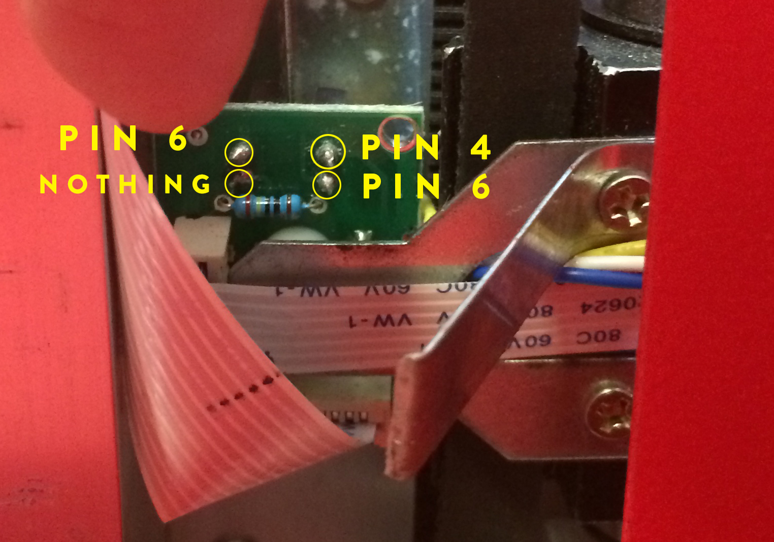
Referring to the picture, please measure the following voltages:
- over the resistor: if this is zero, you're either missing the ground or the Vendstops
- over the top-left and bottom-left pin
- over the top-right and bottom-right pin
The resistor is connected to one of the four pins; to which one? The side the resistor is connected to (left/right) is the LED side. The other side is the detector side.
The detector side: one pin will stay at the same voltage, the other pin will change between high and low indicating homed or not homed. If not: measure the voltage between each pin and ground on the laos board. If that is high (4.5-5V) you're missing a ground connection.
A mechanical endstop should work, but I'm sure we can get this to work as well.
I cannot see the complete endstop pcb, are there more components than the optodetector, resistor and flatcable connectors?
RE: Setting up LS3020 & homing issues
-
Added by jimjiminyjimjim almost 11 years ago
Brilliant thanks - I'll be back in fronts of the laser cutter over the next couple of days - will make all the measurements and get back to you with the results asap.
RE: Setting up LS3020 & homing issues
-
Added by jimjiminyjimjim almost 11 years ago
Ok so after extensive measurement and testing...
Referring to the picture, please measure the following voltages:
- over the resistor: if this is zero, you're either missing the ground or the Vendstops
3.76V
(not sure which left and right is - but lets call this the sensor side (its the black side of the opto sensor)- over the top-left and bottom-left pin
0.05V - 0V
1.12V- over the top-right and bottom-right pin
This is similar readings to the working endstop - apart from the sensor side varies between 0-1V and 3.76V when homed. I receive no reading from the X endstop either homed or not.
So I ordered a brand new set of endstops from HPC + new ribbon cables -to rule everything from the HPC side out. And its made no difference - its exactly the same problem?! New IOtest firmware, clean config files for HPC - so the problem must lie with the LAOS board? Surely?
RE: Setting up LS3020 & homing issues
-
Added by jimjiminyjimjim almost 11 years ago
Would it be possible for anyone to help me with this?
I'm now at a bit of a loss as to what to try next - and I'm basically on the verge of giving up on the LAOS board and put the old electronics back in as I really would like to get the use out of my laser cutter.
Any help would be much appreciated.