Forums » Discussion and support »
 New HPC LS 3020 Setup
Added by drogon over 11 years ago
Hi,
I've emailed Jaap about an issue, but its probably better to post here (I think/hope?) as maybe more have done this...
New LS-3020 - Seems to work OK with their supplied Win XP software (Bleurgh, but it works). Eventually got it going OK after a few emails from HPC who did offer to call at one point, but didn't need it.
In the process of soldering up a v5 LaOS board right now.
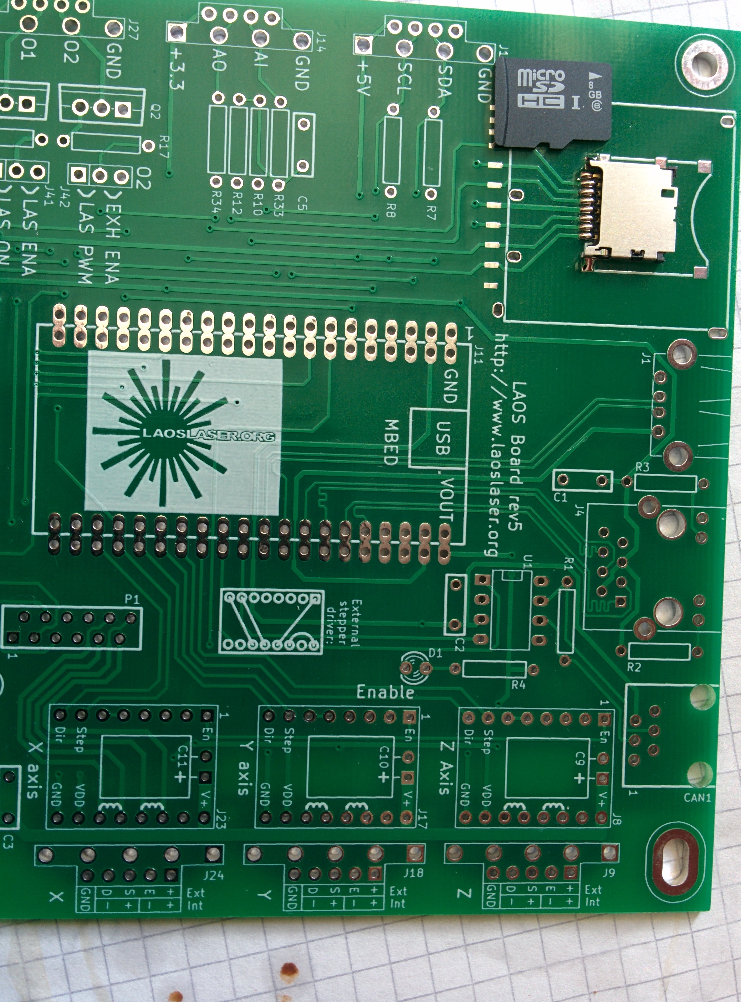
I'm wondering about the µSD card holder. Did I put it on the right way?
http://unicorn.drogon.net/IMG_20140709_140249.jpg
In that photo, the SD card pushes into the holder from the middle of the board towards the edge - in the direction of the arrow on the SD card which I put next to it for reference. Is this right?
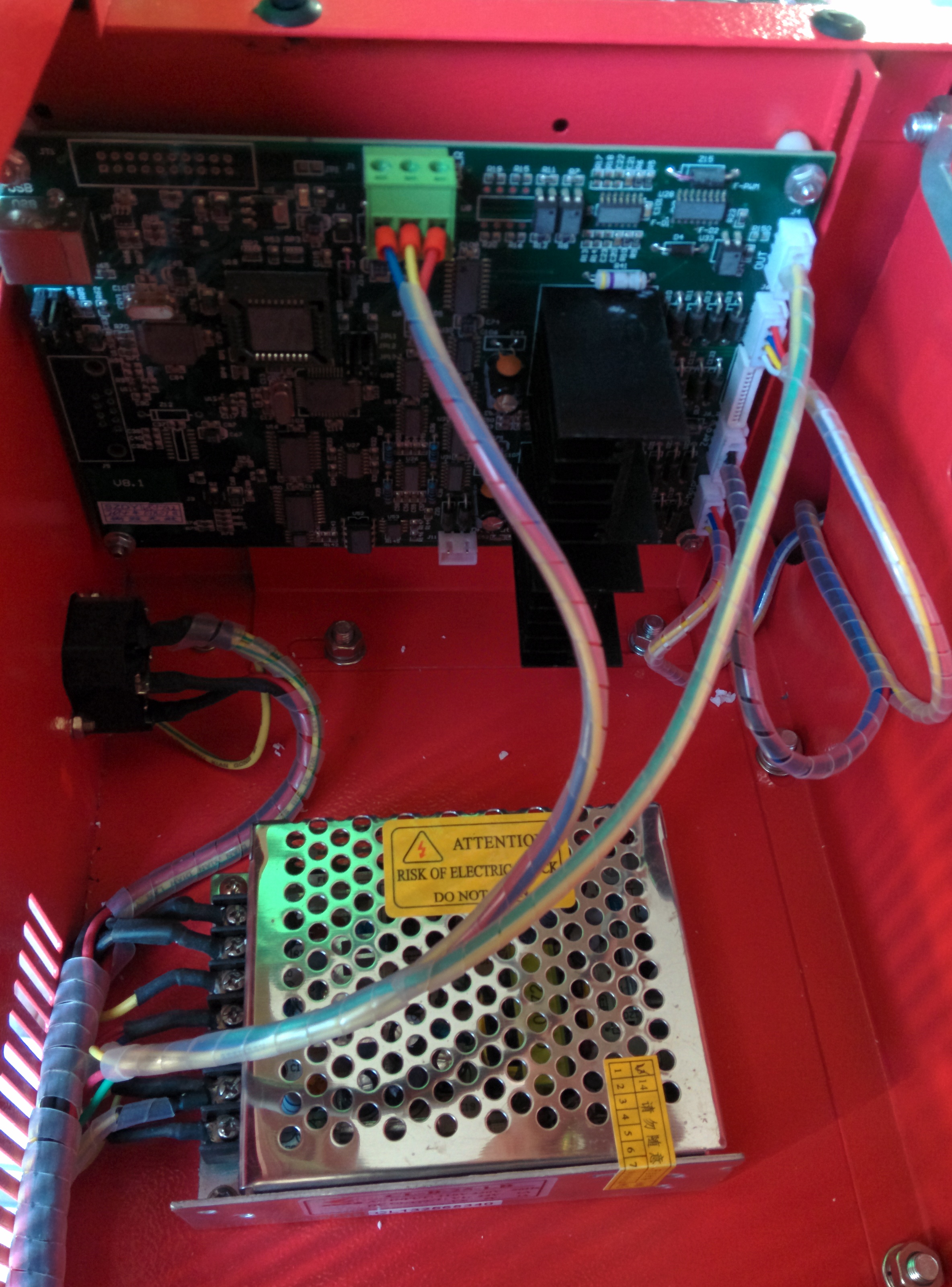
Then there's the LS3020 with its multitude of connectors and options depending on the phase of the Chinese moon by the sounds of it - I bought the "pro" version, but without the software (at least their site says "pro", but it also says it has a 35w laser - the unit I have says it has a 30w laser and they're not yet replied to two questions on that )-:
So my unit appears to have a big 3-pin power plug - 5v on one side, 24v on the other (measured on my multimeter). Does that mean that I should bridge the 7805?
My LS3020 "pro" has 4 JST connectors - I can identify them I think - 2 x 4-way cables coloured red, blue, yellow white are the X&Y steppers I guess, one 2-way cable (green/yellow in the middle 2 pins) is the laser on/off I think, and the final one - 3 wires in a 5-pin connector might be the limit switches?
Picture of the existing PSU and controller board:
http://unicorn.drogon.net/IMG_20140709_183833.jpg
which doesn't seem to resemble the ones I can find on this wiki )-:
So it looks like I have some investigations to do regarding the limit switches - take the 3 wires out of the 5-way header and work out how to put them into the 4-way header on my LaOS board (the common one to V end stops, I guess)
Anyway, almost there. Just got the connectors to solder on, and work out the jumpers, then there's the display board...
And speaking of the display board - there really isn't any space on my panel to put it - the wiki makes mention of lasering a new panel - that would be for everything, buttons, ammeter, keyswitch, etc. ? I guess that's the "and now the apprentice becomes the master" type of thing...
But if anyone has any comments on that SD card holder I'd appreciate it.
Cheers,
-Gordon
Replies (11)
RE: New HPC LS 3020 Setup
-
Added by drogon over 11 years ago
Following my own post up - powered it all up to test, etc. and went through the suggested tests. I checked the voltages on the µSD card and reckoned the 3.3v and 0v were in the right place to take a µSD card, so plugged one in. However nothing. The test program starts, prints the menu, then nothing. (I can see the LED flicker when I type characters on the keyboard though), the main driver program starts but then sticks in a loop complaining about no SD card.
Re-reading the assembly wiki page, it suggests some SD cards might not work )-:
Anyone have a suggestion for one that does work? And must it be 2GB? All I have are 4 and 8's ...
-Gordon
 RE: New HPC LS 3020 Setup
-
Added by jaap over 11 years ago
RE: New HPC LS 3020 Setup
-
Added by jaap over 11 years ago
I think only 2GB cards are supported by the software.
The µSD slot is new on rev 5, I haven't tested it myself yet.
Jaap
RE: New HPC LS 3020 Setup
-
Added by drogon over 11 years ago
Anyone else with a working v5 board? How is your micro SD card holder fitted? Like mine (which is different from the one in the wiki page - that seems an "open" design, mine has a metal covering. This is becoming quite frustrating now )-:
Can anyone confirm that I have soldered it in the right way?
And is there any way to run the software without the SD card?
-Gordon
RE: New HPC LS 3020 Setup
-
Added by jaap over 11 years ago
I just soldered one of these connectors on. It doesn't work for me either. I have a 2GB card in it. Apparently it's the wrong type.
The correct type for MicroSD should be: Molex 502774-0891. However: I didn't test that µSD slot either, so if you want to be on the safe side, using a normal size SD holder (Hirose DM1B-DSF-PEJ) would be best. I can send you one or you can order one from RS or Farnell (that might be faster then shipping from NL).
Jaap
 RE: New HPC LS 3020 Setup
-
Added by Springuin over 11 years ago
RE: New HPC LS 3020 Setup
-
Added by Springuin over 11 years ago
I designed the microSD slot, tested it and it didn't work with the cards I had. So I removed it and placed the regular connector on my board. The idea of a microSD card was a solution designed for situations where you didn't want the card to extend outside of the board.
Can anyone confirm that I have soldered it in the right way?
It looks like your connector accepts a microSD card with the contacts down (the way the card lies in the picture): that's wrong. The Molex 502774-0891 accepts cards with the contacts upwards.
Possible solutions:
- turn the SD card holder 180 degrees (i'm not completely sure if that works).
- get a Molex 502774-0891
- use a normal size SD card holder -> best chance of success.
RE: New HPC LS 3020 Setup
-
Added by drogon over 11 years ago
OK. I'll remove it and order up a full-size card holder for it.
Yea - probably faster if I use Farnell here in the UK.
Actually, I have a dead Pi - might be able to remove the SD holder from that and use it. Won't be able to check until next week though due to other work this weekend now.
Cheers,
-Gordon
RE: New HPC LS 3020 Setup
-
Added by drogon over 11 years ago
Incidentally, the SD card holder that was supplied does not appear to be a Molex 502774-0891. I've no idea what type it is, but the one I was sent bears no resemblance to that part in the photos in the wiki nor the Molex web site.
The connectors on the holder I was sent are definitely designed to have the card facing down - in the way in my photo. The µSD card will not physically fit in any other way.
-Gordon
 RE: New HPC LS 3020 Setup
-
Added by depronman over 11 years ago
RE: New HPC LS 3020 Setup
-
Added by depronman over 11 years ago
drogon wrote:
Incidentally, the SD card holder that was supplied does not appear to be a Molex 502774-0891. I've no idea what type it is, but the one I was sent bears no resemblance to that part in the photos in the wiki nor the Molex web site.
The connectors on the holder I was sent are definitely designed to have the card facing down - in the way in my photo. The µSD card will not physically fit in any other way.
-Gordon
Hi,
I can confirm that the Rev 5 board works perfectly with the full size SD card, I have a 1Gb card in mine and it has held ever cutting job that I have done to date.
My laser is a K40 converted to LaOS, I have a DXF file which I created to accommodate the control panel/display and all the original controls (meter, power knob, buttons, power switch etc). I cut it from 3mm MDF, applied a couple of coats of clear lacquer before installing all the parts. looks good and functional. I offered the DXF for anyone to use in an earlier post, let me know if you want the DXF file.
Cheers,
Paul
 RE: New HPC LS 3020 Setup
-
Added by Rolf over 11 years ago
RE: New HPC LS 3020 Setup
-
Added by Rolf over 11 years ago
I am also having problems with correctly installing the µSD card connector. It would be nice if future boards could have the pin numbers printed on them. Until then, if someone would make a photo or drawing showing the pin numbers, that would be most helpful. Meanwhile I am going to install a standard ST card connector
I have ordered from Mouser a Hirose DM1B-DSF-PEJ that is supposed to be correct from the parts list. However comparing the parts blueprint drawing and the Laos board, it does not seem to be the good match of the pints. Hopefully I am wrong.
This has caused me much frustration :-(
RE: New HPC LS 3020 Setup
-
Added by jaap over 11 years ago
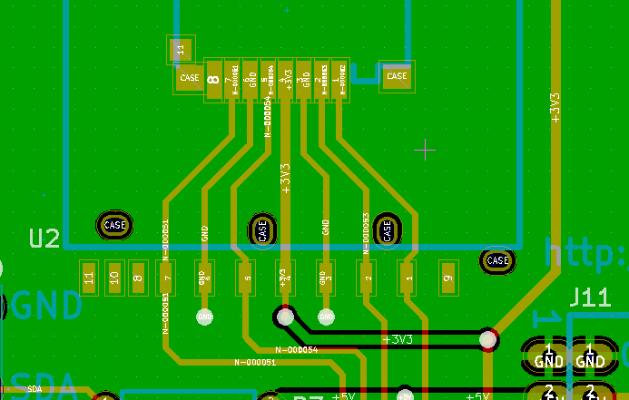
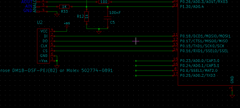
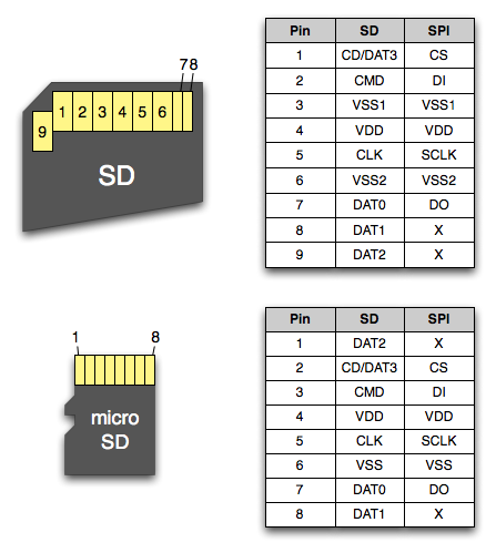
I looked into the µSD issue this morning.
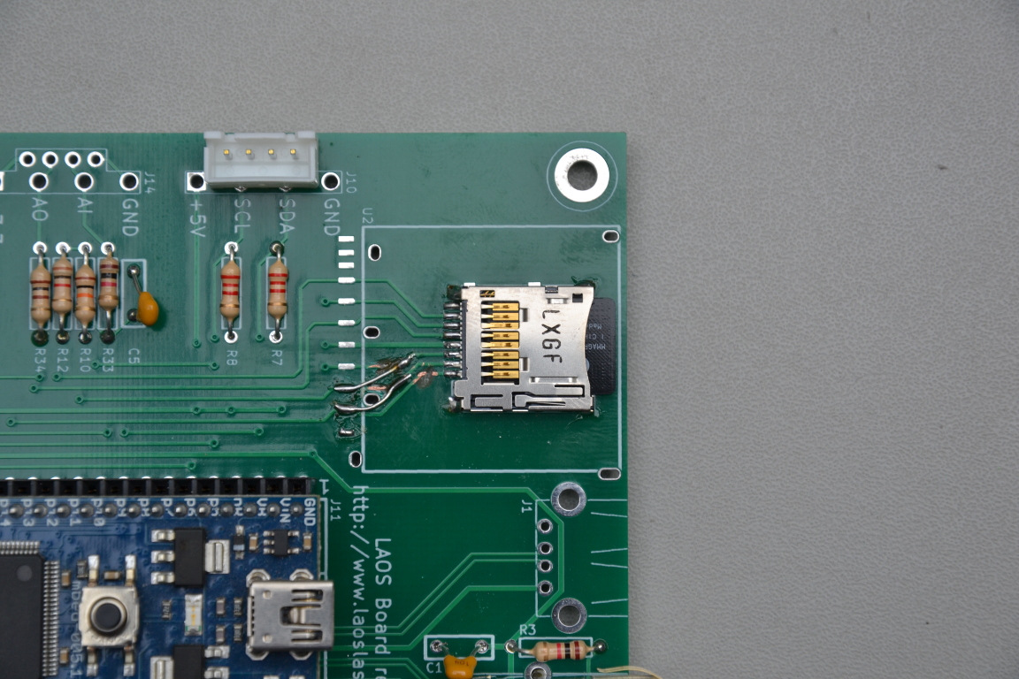
It turns out the pinout of µSD cards differs slightly from those of full size SD cards. This rev0.5 board connects all pins straight from the SD layout to the µSD layout. That doesn't work. But it is possible to get it to work with a bit of cutting and soldering:- Cut the connections for pin 1,2 and 3 of the µSD
- Connect pin 1 of the SD to pin 2 of the µSD
- Connect pin 2 of the SD to pin 3 of the µSD
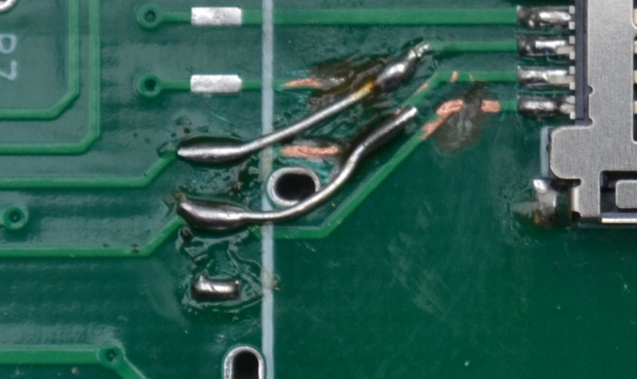
I recommend using a full size SD card when you can. If not, the images here should help you to solder the µSD.
| microsd1.jpg (496 KB) microsd1.jpg | Changes to the board for µSD | ||
| microsd2.jpg (232 KB) microsd2.jpg | Closeup µSD | ||
| boardlayout.png (13.9 KB) boardlayout.png | Board layout | ||
| schematic.png (9.73 KB) schematic.png | SD schema on board | ||
| sd-card-pinout.png (58.5 KB) sd-card-pinout.png | SD card pinout |
RE: New HPC LS 3020 Setup
-
Added by Springuin over 11 years ago
Ah, so that's the problem. I remwmber checking the pinout of the sd and microsd but somewhere between that and the drawing of the pcb shape something must have gone wrong. I will fix this and update the pcb layout.